
HOUSE WIRING_intro

Also Read

Introduction

                               Power is supplied to the domestic installations through, the phase and a neutral, forming a single phase A.C. 230V, two wire system. For industrial establishments, power is supplied through three-phase four-wire system to give 440V. Figure shows the power tapping for domestic and industrial purposes. The neutral is earthed at the sub-station of the supply. As a safe practice all single-phase devices such as switches, fuses etc., are connected to the live conductor. All electrical conductors and cables are colored coded and must be correctly connected up. Electrical wiring is defined as a system of electrical conductors, components and apparatus for conveying electrical power from the source to the point of use. The wiring system must be designed to provide a constant voltage to the load.

Elements of House wiring:

1. Fuses and circuit breakers
2. Electrical switch
3. Plug
4. Socket outlet
5. Lamp holder
6. Ceiling Rose
7. Main switch
8. Incandescent light

Wires and wire sizes:

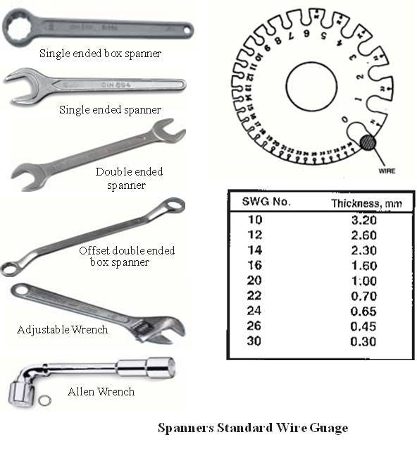
                  A wire is defined as a bare or insulated conductor consisting of one or several strands. An insulated wire consists of a conductor (Silver/Copper/Aluminium) with insulating material made of vulcanized Indian Rubber (VIR) or Poly Vinyl Chloride (PVC). Wire sizes are specified by the diameter of the wire, using a standard wire gauge (SWG), which also gives an idea of the current carrying capacity. The specification consists of both the number of strands and diameter of each wire in it. For Example, the specification 3/18 PVC consists of 3 strands of 18 gauge each.

Various systems of wiring:


  1. Cleat wiring
  2. C.T.S. / T.R.S.Wiring (Cap tyer sheathed/ Tough rubber sheathed wiring)
  3. Wooden casing & capping wiring
  4. Lead sheathed wiring
  5. Conduit wiring
  6. PVC casing & capping

Wiring methods:


1. Series circuit
2. Parallel circuit

Fundamentals of Electricity:

Electrical symbols :

Electricity: Electricity is a form of energy, which cannot be seen. But can be felt and effects like magnetic effect, Heating effect and Chemical effect.

Voltage: It is a pressure which makes the electricity to flow. The unit of measure is Volt. The symbol used is ‘V’. The instrument used to measure is Voltmeter.

Current: The free flow of electrons is called as current. The unit to measure current is ‘Ampere’. The symbol is ‘A’. The instrument used to measure the current is Ammeter. Resistance: It is opposition to current. The unit of resistance is ‘Ohm’. The symbol of ohm is Ω. The resistance is measured by Ohmmeter.

Watt: It is the rate of doing work, when potential difference across the current is of volt and current flowing is ampere per second. 

The energy consumed is of Watt.
1000 Watts = 1 Unit
746 Watts = 1 H.P.
The following are the formulae for calculation.
Voltage V or E = W / I = ÖWR = IR
Current I = E / R = W / E = ÖW / R
Resistance R = E2 / W = E / I = W / I2
Wattage W = I2R = EI = E2 / R

House Wiring Tools:


Combination Pliers : Used for holding, twisting or cutting of wires.

Side cutting Plier: Used for Cutting at narrow places or ordinary places for removing insulation.

Round Nose Plier or Flat Nose Plier: Used for holding, twisting or joining the wire at narrow places.

Firmer Chisel: Used for chipping, scrapping and grooving the wood.

Cold chisel: Used for chipping, Boring and channeling in walls. Tenon saw or back Saw: Used for cutting wooden boards, Block casting etc.

Hack saw: Used for cutting conduit GI pipes or mild steel.

Mallet: Used as a hammer and made of wood Double Blade Electric knife: It has two blades, one for removing insulation of wires and another for cleaning the wires

Soldering Iron: Used to solder small joint terminals Poker: Used for making pilot holes for fixing wood screws.

Line Tester: Used for testing the current.

Royal Plug Tool: It is made of steel and is used for making holes in the stone wall or concrete wall for fibre made Royal plugs.

Screw driver: Used for loosening, tightening and to keep the screws in position.

Ball Peen Hammer: Used for fitting nails in the walls or wooden boards.


Instructions:


  1. When closing the electric switch, always grasp the switch by the insulated handle.
  2. Do not run too many electrical items from one point.
  3. Use fuses and circuit breakers of proper capacity, so as to interrupt the current before it becomes dangerous.
  4. Disconnect the units to be repaired free from power supply and make sure that they might not be energized while the repair work continues.
  5. Do not pour water to put-off fires in electric wires and electric equipment. You will be subjected to electric shock or you will be electrocuted. Use sand to put-off fires in electric items.
  6. Whenever there is power failure, put-off the power supply to all equipment, in order to prevent spontaneous recovery.
  7. Never remove a plug from an outlet by pulling cord. Always pull by holding the plug.
  8. While testing always keep one hand in your packet. If the hands are in contact with a circuit, current will flow across your body and is more dangerous.
  9. Electricity has no respect for ignorance. Do not apply voltage or turn-on any device until it has been properly checked.
  10. Check earth connection before switching on portable equipment

.

Safety Precautions :

1. First we should be insulated
2. Care should be taken while fixing the fuse
3. All the switches should be off before power supply.
4. When power is on, the terminal wires should not be touched


Comments

Fantastic read! This perspective was both refreshing and insightful. I hadn’t considered some of these points before. Thanks for enlightening me. Wall Boxes

Recent posts

Isometric drawings for practice in AutoCAD

What is Isometric Drawing? Isometric drawing is a method of visually representing three-dimensional objects in two dimensions. It allows for a clear and comprehensive depiction of complex structures by keeping the scale consistent and eliminating distortion. Isometric drawings use a 30-degree angle from the horizontal in all three axes (X, Y, and Z), creating a pseudo-3D effect where the height, width, and depth are equally foreshortened. Creating Isometric Drawings in AutoCAD AutoCAD provides tools and settings that make creating isometric drawings straightforward. Here’s a step-by-step guide: Step 1: Set Up Isometric Snap/Grid 1. Enable Isometric Snap/Grid:    - Type `SNAP` in the command line and press `Enter`.    - Type `Style` and press `Enter`.    - Choose `Isometric` and press `Enter`. 2. Switch Between Isoplanes:    - Type `F5` or `CTRL+E` to toggle between the top, right, and left isoplanes. Step 2: Draw Isometric Circles and Arcs 1. Isom...

Sheet metal Funnel making

Making a Funnel using metallic sheet Making a Funnel using metallic sheet Aim:- To make a funnel from a given (GI)metallic sheet. Tools Required:- MALLET, SNIP, STAKE, STEEL RULE, BALL PEEN HAMMER, STRAIGHT EDGE, RIVETS, SCRIBER Procedure:  The size of the given sheet metal is checked for its dimensions using a steel rule The required development of surface is being made on the white paper which is overlapped on the sheet metal. The marking is done on the sheet metal as per the development being done on the paper. Now using straight snips, unwanted materials are removed. Now fold and bend the workpiece to make the funnel shape and joint is made on the workpieces. Then using a groover, a locked grooved joint is made for about 5mm. Also, hemming is done in the bottom of the funnel. In between top face and bottom face, a butt joint is made using a solder. Finally, trimming and finishing operations are carried out. Safety Precautions:- Each cut you make exposes s...

Composite materials Viva Question and Answers

Q1- What is a composite? a. Recycled waste b. A chemical reaction c. The latest computer software d. A structural material consisting of two or more constituents.  Answer: A composite is a structural material which consists of combining two or more constituents Q2- Advanced composites are a. naturally found b. traditionally used in aerospace industries c. low performance composites Answer: Advanced composites are traditionally used in aerospace industries  Q3- Composites are easy to repair a. True b. False Answer:   Composites are generally difficult to repair  Q4- What fiber factors contribute to the mechanical performance of a composite? a. Length b. Orientation c. Shape d. All of the above Answer:   Length, orientation, and shape all contribute to the mechanical performance of a composite  Q5- PMC stands for: a. Polymer Metal Composition b. Polymer Matrix Composite c. Polyethylene Metal Composition Answer:   PMC stands for Polymer Matrix Composite...

MAKING OF A CONE FUNNEL

Ex. No :                                                                                   Date : MAKING OF A CONE FUNNEL Aim To make a funnel from the given sheet metal. Tools required • Steel rule • Mallet • Scriber • Divider • Protractor • Snips • Stakes • Ball peen hammer • Solder Procedure 1. The size of the given sheet is checked for its dimension using           steel rule. 2. The required development of surface is being made on the white       paper which is  overlapped on the sheet metal. 3. The marking is done on the sheet metal as per the development         being done on the  paper. 4. Now using straight snips, unwanted material are removed. 5. Now fold and bend the...

The Motion-Balance System used in Pneumatic Instruments

The motion - balance system is used in pneumatic instruments to produce a proportional output of 3 - 15 psi when a corresponding input signal is applied to the instrument. A typical motion-balance system in a pneumatic instrument is shown below: The above diagram shows a motion-balance system in which the input motion is applied to point P on the lever PQ. The opposite end (Q) of this lever is pivoted to a second lever QRS which in turn has point S pivoted in a lever positioned by movement of the feedback bellows. At the center (R) of the lever QS there is a stem on which one end of the lever RTU is supported while it is pivoted at point U and has a flapper nozzle sensor located at point T. A horizontal displacement which causes P to move to the left is transmitted via Q to R, and as a result the flapper at T moves off the nozzle so that the back pressure falls. This change is amplified by the pneumatic relay so that the pressure in the feedback bellows falls and the lever carrying t...

STRESS STRAIN CHARACTERISTICS OF MILD STEEL BAR BY UTM

Aim: To study the stress strain characteristics of mild steel by Universal Testing Machine Equipment: Universal testing machine meter rule, dividers and scale, Test specimen Theory: In tension test of ductile metals, the properties usually determined are yield strength, ultimate tensile strength, modulus of elasticity, percentage of elongation etc. For brittle materials only compressive strength is determined. The tension test is normally carried out in a Universal Testing Machine (UTM). The specimen can be in the form of a rod or a plate. The dimensions of standard specimen can be known from accepted specifications. The following properties can be determined from the stress strain curve of the material: Proportional limit: is that point on the stress strain curve at which the curve deviates from linearity, i.e. from the relation Stress = Young's modulus x strain $\sigma = E \varepsilon$ Elastic limit: is the point on the stress strain curve above which plastic de...

SINGLE ‘V’ BUTT JOINT

Experiment No.:                                                                                      Date: SINGLE ‘V’ BUTT JOINT Aim: To prepare a single ‘V’ Butt Joint as per dimensions given in the sketch. Material Required: Mild Steel plates: 80mm X 40mm X 6mm = 2 Nos Mild Steel electrode ¢ 3.15 mm Equipment required: A.C. Transformer with all welding accessories like Electrode holder, cables. Tool Required: Steel rule 300mm  Scriber 150mm Flat file 300mm Try square 200mm Flat Tong 450mm  Chipping hammer 200mm Ball peen hammer 750mm  Wire brush Welding screen Sequence of Operations: 1. Marking  2. Filing  3. Welding  4. Finishing Procedure: Take two Mild steel plates of size 80mm X 40mm X 6mm. Fix the wor...

FACING, PLAIN TURNING AND STEP TURNING

Ex. No :                                                                                                          Date : FACING, PLAIN TURNING AND STEP TURNING Aim                       To perform turning, facing and chamfering on a cylindrical work piece. Material used                       Mild steel cylindrical rod. Tools required Lathe Three-jaw chuck Chuck key Vernier caliper Single-point cutting tool Procedure First loosen the jaw in the chuck key to position the work piece, and then tighten the  jaws. Fix the cutting tool in the toolpost. Switch on the lath...

Fluid mechanics VIVA QUESTIONS and ANSWERS

1. Define density? Ans: It is defined as the ratio of mass per unit volume of the fluid. 2. Define viscosity? Ans: It is defined as the property of fluid which offers resistance to the movement of fluid over another adjacent layer of the fluid. 3. Differentiate between real fluids and ideal fluids? Ans: A fluid, which is in-compressible and is having no viscosity, is known as ideal fluid while the fluid, which possesses viscosity, is known as real fluid. 4. What is a venturimeter? Ans: It is a device which is used for measuring the rate of flow of fluid flowing through pipe. 5. What is a notch? Ans: A notch is a device used for measuring the rate of flow of a fluid through a small channel or a tank. 6. Define buoyancy? Ans: When a body is immersed in a fluid, an upward force is exerted by the fluid on the body. This upward force is equal to the weight of the fluid displaced by the body. 7. Define meta-centre? Ans: It is defined as the point about which a body...

Welding VIVA question and answers

VIVA QUESTIONS : Q1: Define welding? Ans:  Welding is a fabrication process that joins two or more materials, typically metals or thermoplastics, by melting and fusing them together using heat or pressure. Q2: What is the typical thickness of MS Plate used in general welding workshop experiments? Ans:  The thickness of the MS (Mild Steel) plate used in general welding workshop experiments can vary depending on the specific requirements of the experiment. However, commonly used thicknesses range from 3 mm to 12 mm. Q3: What is the common job material used in welding experiments? Ans:  The common job material used in welding experiments is mild steel. It is widely available, affordable, and relatively easy to work with, making it suitable for various welding applications and practice. Q4: What is the main function of an electrode in welding? Ans:  The main function of an electrode in welding is to carry the electric current necessary for the welding process and to ...

Search This Blog