
Solidworks FEA step by step exercise - #82

Also Read


1. Select front plane as reference then draw the below shown shape with line elements and dimension it.

2. Now select weldments addon. Then create new structural member using the previous sketch.


3. Now 3 individual weld segments are created like shown below.

4. Now click on simulation feature, Then click on fixed geometry option and select left side face as fixed face.

5. Now add roller constraint to other end using reference geometry option from fixed geometry tool. Then add rigid constraints for 2 directions and leave one direction as free movement end like shown below.

6. Now apply the load on top plane and selected surface like below.

7. Now click on mesh and run option to do simulation.


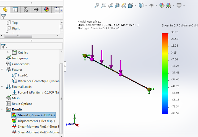
8. Now select right click on results and select beam diagrams to visualize the Bending and shear moment diagrams. 


Comments

Recent posts

Isometric drawings for practice in AutoCAD

What is Isometric Drawing? Isometric drawing is a method of visually representing three-dimensional objects in two dimensions. It allows for a clear and comprehensive depiction of complex structures by keeping the scale consistent and eliminating distortion. Isometric drawings use a 30-degree angle from the horizontal in all three axes (X, Y, and Z), creating a pseudo-3D effect where the height, width, and depth are equally foreshortened. Creating Isometric Drawings in AutoCAD AutoCAD provides tools and settings that make creating isometric drawings straightforward. Here’s a step-by-step guide: Step 1: Set Up Isometric Snap/Grid 1. Enable Isometric Snap/Grid:    - Type `SNAP` in the command line and press `Enter`.    - Type `Style` and press `Enter`.    - Choose `Isometric` and press `Enter`. 2. Switch Between Isoplanes:    - Type `F5` or `CTRL+E` to toggle between the top, right, and left isoplanes. Step 2: Draw Isometric Circles and Arcs 1. Isom...

TIN SMITHY & Sheet metal

TIN SMITHY Introduction : Many engineering and house articles such as boxes, cans, funnels, ducts etc. are made from a flat sheet of metal. The process being known as tin smithy. For this the development of the article is first drawn on the sheet metal, then cut and folded, to form the required shape of the article. Allowance should be given in the drawing stage for folding and bending. This allowance depends upon the radius of the bend and thickness of the sheet metal. Sheet Metal Materials : A variety of metals are used in a sheet metal shop such as galvanized Iron, black, Iron, tin, Stainless Steel, copper and Aluminium. Hand Tools : The common hand tools used in sheet metal work are steel, try square, Wire gauge, Scriber, Ball peen hammer, Nylon Mallet, Snips Divider, Stakes, Cutting plier and Soldering Iron. Here, the details of tools that are being equipped by our workshop purpose only are presented. Wire Gauge: The thickness of sheet is referred in numbers known ...

Fluid mechanics VIVA QUESTIONS and ANSWERS

1. Define density? Ans: It is defined as the ratio of mass per unit volume of the fluid. 2. Define viscosity? Ans: It is defined as the property of fluid which offers resistance to the movement of fluid over another adjacent layer of the fluid. 3. Differentiate between real fluids and ideal fluids? Ans: A fluid, which is in-compressible and is having no viscosity, is known as ideal fluid while the fluid, which possesses viscosity, is known as real fluid. 4. What is a venturimeter? Ans: It is a device which is used for measuring the rate of flow of fluid flowing through pipe. 5. What is a notch? Ans: A notch is a device used for measuring the rate of flow of a fluid through a small channel or a tank. 6. Define buoyancy? Ans: When a body is immersed in a fluid, an upward force is exerted by the fluid on the body. This upward force is equal to the weight of the fluid displaced by the body. 7. Define meta-centre? Ans: It is defined as the point about which a body...

Welding VIVA question and answers

VIVA QUESTIONS : Q1: Define welding? Ans:  Welding is a fabrication process that joins two or more materials, typically metals or thermoplastics, by melting and fusing them together using heat or pressure. Q2: What is the typical thickness of MS Plate used in general welding workshop experiments? Ans:  The thickness of the MS (Mild Steel) plate used in general welding workshop experiments can vary depending on the specific requirements of the experiment. However, commonly used thicknesses range from 3 mm to 12 mm. Q3: What is the common job material used in welding experiments? Ans:  The common job material used in welding experiments is mild steel. It is widely available, affordable, and relatively easy to work with, making it suitable for various welding applications and practice. Q4: What is the main function of an electrode in welding? Ans:  The main function of an electrode in welding is to carry the electric current necessary for the welding process and to ...

step by step procedure to draw hook 2D drawing using AutoCAD

1. Create one vertical line and two horizontal lines like shown below according to dimensions. 2.Draw the circles at intersecting points like shown below with given dimensions. 3. Draw TTR (tangent tangent Radius) circles like shown below with given radius values. 4. Trim extra elements using " TR " command the final image be shown like below. 5. Now draw another reference lines and circles using TTR(tangent tangent Radius) circle according to given dimensions. 6. Now Trim the extra elements by using "TR" command. 7. Now dimension the elements using DIM command.

SINGLE ‘V’ BUTT JOINT

Experiment No.:                                                                                      Date: SINGLE ‘V’ BUTT JOINT Aim: To prepare a single ‘V’ Butt Joint as per dimensions given in the sketch. Material Required: Mild Steel plates: 80mm X 40mm X 6mm = 2 Nos Mild Steel electrode ¢ 3.15 mm Equipment required: A.C. Transformer with all welding accessories like Electrode holder, cables. Tool Required: Steel rule 300mm  Scriber 150mm Flat file 300mm Try square 200mm Flat Tong 450mm  Chipping hammer 200mm Ball peen hammer 750mm  Wire brush Welding screen Sequence of Operations: 1. Marking  2. Filing  3. Welding  4. Finishing Procedure: Take two Mild steel plates of size 80mm X 40mm X 6mm. Fix the wor...

MOULD WITH SPLIT PATTERN

Ex. No :                                                                                       Date : MOULD WITH SPLIT PATTERN Aim To make the mould for the given split pattern. Material required •  Moulding board •  Riser pin •  Moulding box •  Sprue pin •  Green sand •  Rammer •  Trowel •  Lifter •  Riddle •  Draw spike •  Gate cutter  •  Bellow •  Vent rod  Procedure 1. Place the moulding board on a horizontal surface. 2. The drag box is placed above the moulding board. Now one piece      of pattern is kept at  center of the drag as shown in figure. 3. The parting sand is spread before we keep the pattern. 4. Facing sand is spri...

Welding-LAP JOINT

Ex. No :                                                                              Date : LAP JOINT Aim To join the given two work pieces as a lap joint by arc welding. Material used Mild Steel plates. Tools required Welding power supply  Flat file Welding rod Chipping hammer Electrode holder Wire brush Gloves and apron Earthing clamps Shield and goggles Procedure The given workpieces are thoroughly cleaned, i.e. rust, scales are removed and the  edges are filed. The electrode is held in an electrode holder and ground clamp is clamped to the  welding plates and the power is supplied. The workpieces are positioned on the table to form a “Lab joint”. The tag weld is done on the both the ends of joining plates to avoid the m...

Sheet metal Funnel making

Making a Funnel using metallic sheet Making a Funnel using metallic sheet Aim:- To make a funnel from a given (GI)metallic sheet. Tools Required:- MALLET, SNIP, STAKE, STEEL RULE, BALL PEEN HAMMER, STRAIGHT EDGE, RIVETS, SCRIBER Procedure:  The size of the given sheet metal is checked for its dimensions using a steel rule The required development of surface is being made on the white paper which is overlapped on the sheet metal. The marking is done on the sheet metal as per the development being done on the paper. Now using straight snips, unwanted materials are removed. Now fold and bend the workpiece to make the funnel shape and joint is made on the workpieces. Then using a groover, a locked grooved joint is made for about 5mm. Also, hemming is done in the bottom of the funnel. In between top face and bottom face, a butt joint is made using a solder. Finally, trimming and finishing operations are carried out. Safety Precautions:- Each cut you make exposes s...

AutoCAD practice parts for Learners

Hi all! The below table contains some of the AutoCAD practice drawings with step by step procedure links. please visit the links to see all details of the draiwngs. Practice drawing Details Remarks Intoduction to AutoCAD Procedure steps in AutoCAD. Procedure in YOUTUBE. Download AutoCAD drawing files. You have any projects or quaries please contact us! Basic settings of drawing in AutoCAD Procedure steps in AutoCAD. Procedure in YOUTUBE. Download AutoCAD drawing files. You have any projects or quaries please contact us! Drafting settings in AutoCAD Procedure steps in AutoCAD. Procedure in YOUTUBE. Download AutoCAD drawing files. You have any projects or quaries please contact us! ...

Search This Blog