
TIN SMITHY & Sheet metal

Also Read

TIN SMITHY

Introduction :

Many engineering and house articles such as boxes, cans, funnels, ducts etc. are made from a flat sheet of metal. The process being known as tin smithy. For this the development of the article is first drawn on the sheet metal, then cut and folded, to form the required shape of the article. Allowance should be given in the drawing stage for folding and bending. This allowance depends upon the radius of the bend and thickness of the sheet metal.

Sheet Metal Materials :
A variety of metals are used in a sheet metal shop such as galvanized Iron, black, Iron, tin, Stainless Steel, copper and Aluminium.
Hand Tools :

The common hand tools used in sheet metal work are steel, try square, Wire gauge, Scriber, Ball peen hammer, Nylon Mallet, Snips Divider, Stakes, Cutting plier and Soldering Iron. Here, the details of tools that are being equipped by our workshop purpose only are presented.
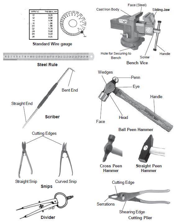
Wire Gauge: The thickness of sheet is referred in numbers known as standard wire gauge (SWG). The gaps in the circumference of the gauge are used to check the gauge number.
Steel Rule : It is a strip of steel with graduations on its edges. It is used for measuring and setting out dimensions.
Scriber : A scriber is a slender steel tool, used to scribe or mark lines on sheet metal.
Snips : Hand shears or snips are used to cut sheet metal.
Straight Snips: These are having straight blades and are used for cutting along straight lines and fortrimming edges.
Curved Snips:These are having curved blades and are used for cutting circles and irregular shapes.
Divider: It consists of two pointed legs. The points are hardened and tempered to prevent wear. It is used for transferring the sizes and scribing curves or circles.
Bench vice: It is generally used for holding and bending the work piece.
Hammers: Light weight hammers and mallets are used in sheet metal work.
Ball Peen Hammer: It has a cylindrical, slightly curved face and a ball head. It is a general purpose hammer used mostly for riveting in sheet metal work.
Cross Peen Hammer: It has a tapered peen end and is perpendicular to the handle. Because of this, it can reach awkward corners.
Straight Peen Hammer: It has the peen end similar to the cross peen, but it is positioned parallel to the handle which can be used conveniently for certain operations of folding.
Cutting Plier: Used for holding, cutting and bending works.
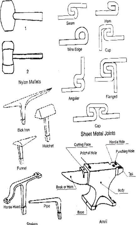
Nylon Mallet: It is used for bending and folding work. It is light in weight, covers more area and do not damage the surface area.
Stakes: Stakes are made of steel and forged in a variety of shapes and sizes. These are used as supporting tool and to form, seam, bend or rivet sheet metal objects.
Anvil: Anvil provides the necessary support during hammering. It is also useful for operations such as bending. Its body is generally made of mild steel and a strip of high carbon steel about 20 mm thick is welded on top to provide hard face.
Sheet Metal Joints :
Various types of joints are used in sheet metal work, to suit the varying requirement. Some commonly used sheet metal joints and folded edges are shown in the figure. These are self-secured joints, formed by joining together two pieces of GI sheet metal and using the metal itself to form the joint.
Sheet Metal Layout :
The shapes of most articles made with sheet metal are in few geometrical forms. All these forms are made from flat sheet; therefore the first requirement is developing the lines, which forms the pattern. The development or stretch out of a job is called pattern and developing lines which forms a pattern is layout. It may be drawn on paper first and then transferred in the sheet or it may latyout directly on sheet metal. When a pattern is made repeatedly, it is generally made of metal and referred to as a template.

Insturctions:

  1. Draw the development of object to be prepared with true dimensions only.
  2. Use curved snip for trimming along inside curves.
  3. Always provide folding (Hem) for top edges of the object to avoid sharp edges and to stiffen the sheet.
  4. Ground properly the exposed metal parts of electrically heated soldering iron.
  5. For good soldering the metals to be joined must free from dirt, grease and oxide.
  6. Do not pull (or) peel the cut portion by hand while cutting with snip.
  7. Do not bend the sheet with hand, always use nylon mallet with proper support.

Safetry Precautions :

  1. Use hand leather gloves while handling heavy sheets.
  2. Avoid feeling the cut portion by hand while cutting with snip.
  3. Do not let sheet metal slip through the hands.
  4. Never carry tools in pockets.

Exercise:
1. Plain pipe
2. Rectangular tray
3. Triangular tray
4. Funnel

Comments

Unknown said…
This comment has been removed by a blog administrator.
Unknown said…
Checkout our website for various kinds of axes
Axe Selector
Henchman said…
Great blog! Your blog is very helpful. Sheet metal is considered to be the most basic type of metalworking. Purchase quality sheet metal toolkits and tools from anywhere across the world with Henchman Products.
Veer O Metals said…
Thank you for sharing this blog.
For Stamped Parts : Machined components
Vincent said…
Nice informative blog. Thanks for sharing and keep it up.
Grease duct wrap
RNA Heating said…
I recently had a great experience with RNA Heating when I needed a Boiler Repair in Kidderminster. The engineer was polite, punctual, and very knowledgeable. He quickly found the fault and fixed it without any hassle. The service was professional, affordable, and carried out to a high standard. It’s rare to find a company that communicates clearly and genuinely cares about its customers. I now have heating and hot water again thanks to RNA Heating. If anyone needs a trustworthy and efficient boiler repair in Kidderminster, I highly recommend this team. Excellent service from start to finish!

Recent posts

PLUMBING Introduction Plumbing deals with the laying of a pipeline. A craftsman may be perfectly proficient with the hammer, saw and other tools, but the faces difficulties with leaking pipes and overflowing toilets. Many people rush to a plumber on seeking a tripping pipe, but a person with a little knowledge of the sanitary system can control this problem easily, saving time and, one with help of few tools. Plumbing tools The tools used by a plumber can be classified as follows Pipe wrench  Pipe vice Pipe cutter Hacksaw  Dies Files and Rasps Plumb bob Pipe wrench A pipe wrench is used for holding and turning the pipes, rods and machine prts. Wrenches are classified as follows. 1.Fixed wrenches  2. Adjustable wrenches. Pipe vice A pipe vice is fitted on the work bench. This has a set of jaws to grip the pipe and prevent it from turning while cutting, threading and fitting of bends, couplings etc. The yoke vice is co...

Isometric drawings for practice in AutoCAD

What is Isometric Drawing? Isometric drawing is a method of visually representing three-dimensional objects in two dimensions. It allows for a clear and comprehensive depiction of complex structures by keeping the scale consistent and eliminating distortion. Isometric drawings use a 30-degree angle from the horizontal in all three axes (X, Y, and Z), creating a pseudo-3D effect where the height, width, and depth are equally foreshortened. Creating Isometric Drawings in AutoCAD AutoCAD provides tools and settings that make creating isometric drawings straightforward. Here’s a step-by-step guide: Step 1: Set Up Isometric Snap/Grid 1. Enable Isometric Snap/Grid:    - Type `SNAP` in the command line and press `Enter`.    - Type `Style` and press `Enter`.    - Choose `Isometric` and press `Enter`. 2. Switch Between Isoplanes:    - Type `F5` or `CTRL+E` to toggle between the top, right, and left isoplanes. Step 2: Draw Isometric Circles and Arcs 1. Isom...

Fluid mechanics VIVA QUESTIONS and ANSWERS

1. Define density? Ans: It is defined as the ratio of mass per unit volume of the fluid. 2. Define viscosity? Ans: It is defined as the property of fluid which offers resistance to the movement of fluid over another adjacent layer of the fluid. 3. Differentiate between real fluids and ideal fluids? Ans: A fluid, which is in-compressible and is having no viscosity, is known as ideal fluid while the fluid, which possesses viscosity, is known as real fluid. 4. What is a venturimeter? Ans: It is a device which is used for measuring the rate of flow of fluid flowing through pipe. 5. What is a notch? Ans: A notch is a device used for measuring the rate of flow of a fluid through a small channel or a tank. 6. Define buoyancy? Ans: When a body is immersed in a fluid, an upward force is exerted by the fluid on the body. This upward force is equal to the weight of the fluid displaced by the body. 7. Define meta-centre? Ans: It is defined as the point about which a body...

SINGLE ‘V’ BUTT JOINT

Experiment No.:                                                                                      Date: SINGLE ‘V’ BUTT JOINT Aim: To prepare a single ‘V’ Butt Joint as per dimensions given in the sketch. Material Required: Mild Steel plates: 80mm X 40mm X 6mm = 2 Nos Mild Steel electrode ¢ 3.15 mm Equipment required: A.C. Transformer with all welding accessories like Electrode holder, cables. Tool Required: Steel rule 300mm  Scriber 150mm Flat file 300mm Try square 200mm Flat Tong 450mm  Chipping hammer 200mm Ball peen hammer 750mm  Wire brush Welding screen Sequence of Operations: 1. Marking  2. Filing  3. Welding  4. Finishing Procedure: Take two Mild steel plates of size 80mm X 40mm X 6mm. Fix the wor...

ROCKWELL HARDNESS TEST

Aim :-To determine the Rockwell hardness for the given test specimen Equipment :-Rockwell Hardness Testing Machine,suitable indenter, test specimens. Description :-Hardness may be defined as resistance of metal to plastic deformation usually by indentation. However the term may also refer to stiffness or temper or resistance to scratch, abrasion or cutting. There are three general types of hardness measurements depending upon the manner in which the test is conducted. Scratch hardness measurement. Rebound hardness measurement. Indentation Hardness measurement. In scratch hardness method the materials are rated on their ability to scratch one another and mineralogists use it. In rebound hardness measurement, a standard body is usually dropped on to the material surface and the hardness is measured in terms of the height of its rebound. The general means of judging the hardness is the resistance of a material to indentation. Indentation hardness may be measured by various h...

Sheet metal Funnel making

Making a Funnel using metallic sheet Making a Funnel using metallic sheet Aim:- To make a funnel from a given (GI)metallic sheet. Tools Required:- MALLET, SNIP, STAKE, STEEL RULE, BALL PEEN HAMMER, STRAIGHT EDGE, RIVETS, SCRIBER Procedure:  The size of the given sheet metal is checked for its dimensions using a steel rule The required development of surface is being made on the white paper which is overlapped on the sheet metal. The marking is done on the sheet metal as per the development being done on the paper. Now using straight snips, unwanted materials are removed. Now fold and bend the workpiece to make the funnel shape and joint is made on the workpieces. Then using a groover, a locked grooved joint is made for about 5mm. Also, hemming is done in the bottom of the funnel. In between top face and bottom face, a butt joint is made using a solder. Finally, trimming and finishing operations are carried out. Safety Precautions:- Each cut you make exposes s...

Step by step procedure to insert 3rd Angle Projection symbol in Solidworks

Step 1: open solidworks drawing tool with default or your required sheet size. Then the object view in paper space. Step 2: 1. Click on Annotation tab and select "Note". 2. Then add the note at title block. 3. Then click on add symbol in properties manager. 4. Then click on add more symbols. Step 3: Check the symbol in symbol library categories. if you found the symbol then click on "OK" button. if you not found the 3rd angle projection in the symbol library categories then see the Step 4 in this page. Step 4: 1. Go to this file location from your computer by pasting the below in your windows explorer or browse from your computer or search "gtol.sym" and open the file location by using right clicking on the searchable file. C:\ProgramData\SOLIDWORKS\SOLIDWORKS 2019\lang\english 2. Then copy the "gtol.sym" file then paste this file in anywhere you like. here i'm pasting this file in desktop > Solidworks > pr...

Welding introduction

WELDING Introduction : Welding is a process of joining two similar or dissimilar metals by the application of heat with or without application of pressure and addition of filler material. The welding is extensively used in manufacturing industry, construction industry and maintenance work, replacing riveting and bolting, to a greater extent.  The various welding processes are 1. Electric arc welding 2. Gas welding 3. Thermit welding 4. Resistance welding and 5. Friction welding However only electric arc welding is discussed here. In this process, the work pieces are melted along a common edge, to their melting point and then a filler metal is introduced to form the joint on solidification. The materials to be welded must be free from rust, scale oil or other impurities, so as to obtain a sound weld. Arc Welding: In arc welding, the heat required for joining the metals is obtained from an electric arc. Transformers or motor generator sets are used as arc welding ma...

Welding-LAP JOINT

Ex. No :                                                                              Date : LAP JOINT Aim To join the given two work pieces as a lap joint by arc welding. Material used Mild Steel plates. Tools required Welding power supply  Flat file Welding rod Chipping hammer Electrode holder Wire brush Gloves and apron Earthing clamps Shield and goggles Procedure The given workpieces are thoroughly cleaned, i.e. rust, scales are removed and the  edges are filed. The electrode is held in an electrode holder and ground clamp is clamped to the  welding plates and the power is supplied. The workpieces are positioned on the table to form a “Lab joint”. The tag weld is done on the both the ends of joining plates to avoid the m...

step by step procedure to draw hook 2D drawing using AutoCAD

1. Create one vertical line and two horizontal lines like shown below according to dimensions. 2.Draw the circles at intersecting points like shown below with given dimensions. 3. Draw TTR (tangent tangent Radius) circles like shown below with given radius values. 4. Trim extra elements using " TR " command the final image be shown like below. 5. Now draw another reference lines and circles using TTR(tangent tangent Radius) circle according to given dimensions. 6. Now Trim the extra elements by using "TR" command. 7. Now dimension the elements using DIM command.

Search This Blog