
INTRODUCTION TO AUTOCAD

Also Read

AutoCAD is a program designed for draw the drawings, for example in mechanical engineering, civil engineering and surveying. There can be two-dimensional design drawings in terms of (2D) and three-dimensional view (3D) in the case (drawing), which lines.
Working in AutoCAD requires some basic knowledge of your work, and also good to have prior knowledge base and knowledge of the plot coordinate system.
AutoCAD is a low cost yet very effective computer aided design and drafting software.

Some of the advantages of CAD over manual drawing are:

  • No need for scaling. We can create all drawings  in full size.
  • The screen drawing area can be set to any size with the click of a button.
  • The program supplies all of the tools needed.
  • Absolute accuracy can be maintained.
  • Production details can be extracted directly from the drawing.
  • Eliminates the need for full size set outs.
  • Both two and three-dimensional drawings can be produced.
  • Your work is copied and store off the computer for security – you may never lose your work again.
  • Drawings are stored on disk rather than in a bulky folder.
  • Dimensioning is almost automatic.
  • Parts of drawings can be saved and used in other drawings.

  • Example of Autocad drawing

    example of autocad drawing airoplane line daigram


    Starting up AutoCAD

    If you install AutoCAD 2008 using default settings for the location of program file, start AutoCAD by choosing
    Start ⇒ Programs ⇒ Autodesk ⇒ AutoCAD 2008
    Or
    double click on AutoCAD 2008 Icon on your desktop

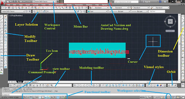
    AutoCAD 2008 Interface


    Menu Bar: Contains the default AutoCAD menus.

    Standard Toolbar: This contains the frequently used buttons such as Zoom, Undo and Redraw. It also has the Microsoft Standard buttons.

    Drawing tools and modify toolbars: These toolbars provide you with the common draw and modify commands.

    Cross-hairs: The cross-hairs are controlled by the mouse, to locate points and select and draw objects.

    Command window: The command window displays messages and prompts.

    In AutoCAD there are three ways of initiating commands.
    1. Click a button on a tool bar
    2. Choose an item from a menu.
    3. Enter the command on the command line.
    Autocad 2014 Interface:


    Back button

    Comments

    Recent posts

    Isometric drawings for practice in AutoCAD

    What is Isometric Drawing? Isometric drawing is a method of visually representing three-dimensional objects in two dimensions. It allows for a clear and comprehensive depiction of complex structures by keeping the scale consistent and eliminating distortion. Isometric drawings use a 30-degree angle from the horizontal in all three axes (X, Y, and Z), creating a pseudo-3D effect where the height, width, and depth are equally foreshortened. Creating Isometric Drawings in AutoCAD AutoCAD provides tools and settings that make creating isometric drawings straightforward. Here’s a step-by-step guide: Step 1: Set Up Isometric Snap/Grid 1. Enable Isometric Snap/Grid:    - Type `SNAP` in the command line and press `Enter`.    - Type `Style` and press `Enter`.    - Choose `Isometric` and press `Enter`. 2. Switch Between Isoplanes:    - Type `F5` or `CTRL+E` to toggle between the top, right, and left isoplanes. Step 2: Draw Isometric Circles and Arcs 1. Isom...

    TIN SMITHY & Sheet metal

    TIN SMITHY Introduction : Many engineering and house articles such as boxes, cans, funnels, ducts etc. are made from a flat sheet of metal. The process being known as tin smithy. For this the development of the article is first drawn on the sheet metal, then cut and folded, to form the required shape of the article. Allowance should be given in the drawing stage for folding and bending. This allowance depends upon the radius of the bend and thickness of the sheet metal. Sheet Metal Materials : A variety of metals are used in a sheet metal shop such as galvanized Iron, black, Iron, tin, Stainless Steel, copper and Aluminium. Hand Tools : The common hand tools used in sheet metal work are steel, try square, Wire gauge, Scriber, Ball peen hammer, Nylon Mallet, Snips Divider, Stakes, Cutting plier and Soldering Iron. Here, the details of tools that are being equipped by our workshop purpose only are presented. Wire Gauge: The thickness of sheet is referred in numbers known ...

    Fluid mechanics VIVA QUESTIONS and ANSWERS

    1. Define density? Ans: It is defined as the ratio of mass per unit volume of the fluid. 2. Define viscosity? Ans: It is defined as the property of fluid which offers resistance to the movement of fluid over another adjacent layer of the fluid. 3. Differentiate between real fluids and ideal fluids? Ans: A fluid, which is in-compressible and is having no viscosity, is known as ideal fluid while the fluid, which possesses viscosity, is known as real fluid. 4. What is a venturimeter? Ans: It is a device which is used for measuring the rate of flow of fluid flowing through pipe. 5. What is a notch? Ans: A notch is a device used for measuring the rate of flow of a fluid through a small channel or a tank. 6. Define buoyancy? Ans: When a body is immersed in a fluid, an upward force is exerted by the fluid on the body. This upward force is equal to the weight of the fluid displaced by the body. 7. Define meta-centre? Ans: It is defined as the point about which a body...

    SINGLE ‘V’ BUTT JOINT

    Experiment No.:                                                                                      Date: SINGLE ‘V’ BUTT JOINT Aim: To prepare a single ‘V’ Butt Joint as per dimensions given in the sketch. Material Required: Mild Steel plates: 80mm X 40mm X 6mm = 2 Nos Mild Steel electrode ¢ 3.15 mm Equipment required: A.C. Transformer with all welding accessories like Electrode holder, cables. Tool Required: Steel rule 300mm  Scriber 150mm Flat file 300mm Try square 200mm Flat Tong 450mm  Chipping hammer 200mm Ball peen hammer 750mm  Wire brush Welding screen Sequence of Operations: 1. Marking  2. Filing  3. Welding  4. Finishing Procedure: Take two Mild steel plates of size 80mm X 40mm X 6mm. Fix the wor...

    sheet metal rectangular tray making

    Aim :- To make a rectangular tray from a given metallic sheet. Tools Required MALLET Snip Stake STEEL RULE Ball peen HAMMER Straight EDGE RIVETS Scriber Procedure The given metal sheet is smoothed using mallet. The measurements of rectangular tray (tray development drawing) is drawn on the sheet with given dimensions using the scriber and steel rule. The sheet is cut as per the marked dimensions by straight snips. Fold or bend as per the given order using mallet and stake. Bending is done as per the given dimension using the stake and mallet. Rivet the folded sheet by using the given rivets and hammer. Safety Precautions Each cut you make exposes sharp edges and creates burrs that can slice a finger. Must Use Hand gloves when cutting the sheet. Metal waste also has hazardous edges. So...

    Welding-LAP JOINT

    Ex. No :                                                                              Date : LAP JOINT Aim To join the given two work pieces as a lap joint by arc welding. Material used Mild Steel plates. Tools required Welding power supply  Flat file Welding rod Chipping hammer Electrode holder Wire brush Gloves and apron Earthing clamps Shield and goggles Procedure The given workpieces are thoroughly cleaned, i.e. rust, scales are removed and the  edges are filed. The electrode is held in an electrode holder and ground clamp is clamped to the  welding plates and the power is supplied. The workpieces are positioned on the table to form a “Lab joint”. The tag weld is done on the both the ends of joining plates to avoid the m...

    Welding introduction

    WELDING Introduction : Welding is a process of joining two similar or dissimilar metals by the application of heat with or without application of pressure and addition of filler material. The welding is extensively used in manufacturing industry, construction industry and maintenance work, replacing riveting and bolting, to a greater extent.  The various welding processes are 1. Electric arc welding 2. Gas welding 3. Thermit welding 4. Resistance welding and 5. Friction welding However only electric arc welding is discussed here. In this process, the work pieces are melted along a common edge, to their melting point and then a filler metal is introduced to form the joint on solidification. The materials to be welded must be free from rust, scale oil or other impurities, so as to obtain a sound weld. Arc Welding: In arc welding, the heat required for joining the metals is obtained from an electric arc. Transformers or motor generator sets are used as arc welding ma...

    step by step procedure to draw hook 2D drawing using AutoCAD

    1. Create one vertical line and two horizontal lines like shown below according to dimensions. 2.Draw the circles at intersecting points like shown below with given dimensions. 3. Draw TTR (tangent tangent Radius) circles like shown below with given radius values. 4. Trim extra elements using " TR " command the final image be shown like below. 5. Now draw another reference lines and circles using TTR(tangent tangent Radius) circle according to given dimensions. 6. Now Trim the extra elements by using "TR" command. 7. Now dimension the elements using DIM command.
    PLUMBING Introduction Plumbing deals with the laying of a pipeline. A craftsman may be perfectly proficient with the hammer, saw and other tools, but the faces difficulties with leaking pipes and overflowing toilets. Many people rush to a plumber on seeking a tripping pipe, but a person with a little knowledge of the sanitary system can control this problem easily, saving time and, one with help of few tools. Plumbing tools The tools used by a plumber can be classified as follows Pipe wrench  Pipe vice Pipe cutter Hacksaw  Dies Files and Rasps Plumb bob Pipe wrench A pipe wrench is used for holding and turning the pipes, rods and machine prts. Wrenches are classified as follows. 1.Fixed wrenches  2. Adjustable wrenches. Pipe vice A pipe vice is fitted on the work bench. This has a set of jaws to grip the pipe and prevent it from turning while cutting, threading and fitting of bends, couplings etc. The yoke vice is co...

    Sheet metal Funnel making

    Making a Funnel using metallic sheet Making a Funnel using metallic sheet Aim:- To make a funnel from a given (GI)metallic sheet. Tools Required:- MALLET, SNIP, STAKE, STEEL RULE, BALL PEEN HAMMER, STRAIGHT EDGE, RIVETS, SCRIBER Procedure:  The size of the given sheet metal is checked for its dimensions using a steel rule The required development of surface is being made on the white paper which is overlapped on the sheet metal. The marking is done on the sheet metal as per the development being done on the paper. Now using straight snips, unwanted materials are removed. Now fold and bend the workpiece to make the funnel shape and joint is made on the workpieces. Then using a groover, a locked grooved joint is made for about 5mm. Also, hemming is done in the bottom of the funnel. In between top face and bottom face, a butt joint is made using a solder. Finally, trimming and finishing operations are carried out. Safety Precautions:- Each cut you make exposes s...

    Search This Blog