
Step by step procedure to insert 3rd Angle Projection symbol in Solidworks

Also Read


Step 1:
open solidworks drawing tool with default or your required sheet size.
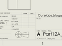
Then the object view in paper space.

Step 2:
1. Click on Annotation tab and select "Note".
2. Then add the note at title block.
3. Then click on add symbol in properties manager.
4. Then click on add more symbols.


Step 3:
Check the symbol in symbol library categories. if you found the symbol then click on "OK" button. if you not found the 3rd angle projection in the symbol library categories then see the Step 4 in this page.


Step 4:
1. Go to this file location from your computer by pasting the below in your windows explorer or browse from your computer or search "gtol.sym" and open the file location by using right clicking on the searchable file.

C:\ProgramData\SOLIDWORKS\SOLIDWORKS 2019\lang\english

2. Then copy the "gtol.sym" file then paste this file in anywhere you like.
here i'm pasting this file in desktop > Solidworks > projection folder.


Step 5:
Then open the folder where you paste the "gtol.sym" file.
Right click on the "gtol.sym" file then select open with Notepad application. see the below image for full steps.


Then paste the code after last line of the opened document.

;;
;;
;;----------------------------------------------------------------------
;; https://ourelabs.blogspot.com
;;
#projection_symbols
*THIRD, Third Angle Projection
A,CIRCLE .5,.5,.25
A,CIRCLE .5,.5,.46
A,LINE 0,.5,2,.5
A,LINE .5,0,.5,1
A,LINE 1.1,.25,1.1,.75
A,LINE 1.1,.25,1.88,.08
A,LINE 1.1,.75,1.88,.92
A,LINE 1.88,.08,1.88,.92
*FIRST, First Angle Projection
A,LINE .22,.25,.22,.75
A,LINE .22,.75,1,.92
A,LINE 1,.92,1,.08
A,LINE 1,.08,.22,.25
A,LINE 1.6,1,1.6,0
A,LINE .11,.5,2.11,.5
A,CIRCLE 1.6,.5,.25
A,CIRCLE 1.6,.5,.46


Then save the file by pressing "ctrl+s" keys.
Then close the "gtol.sym" file.

Step 6:
1. Click on options button.
2. select "System options" tab.
3. Select "File Locations" option.
4.Select "Symbol library file" from drop down list. and select current folder in folder box and Click on "Delete" button.
5. Then click on "Add" button.
6. Now browse the folder that contains you edited "gtol.sym" file location.
7. Select "Select folder" button.
And click on "OK" button in system options dialog box.


Then save the drawing file and close the solidworks software. And re open the saved file.

Step 7:
1. Now again Click on "Note" from "Annotation" tab.
2. Add a text box.
3. Now click on add symbol from "Note" property manager and click on "More symbols" from the pop up.
4. Make sure the "Symbol Library" file location is your edited "gtol.sym" file location or not.
Note: if file location is not correct then again do the step 6.
5. Now select symbol category type.
6. Then select your required symbol.
7. Then select "OK" button from symbol library dialog box.


Step 8:
Now added the third angle projection symbol in the text box now adjust the size by using formatting tool bar.


Comments

Fire fighting said…
Thanks for sharing such a nice blog with full information, we are looking forward to see more blogs in future. We at Kartar Valves understand the expectations of our customers and are continuously meeting the challenge of making three essentials available to our customer viz: Best Quality, Right Price & Timely Deliveries. Cast Iron Ball Valve Manufacturers

Recent posts

Fluid mechanics VIVA QUESTIONS and ANSWERS

1. Define density? Ans: It is defined as the ratio of mass per unit volume of the fluid. 2. Define viscosity? Ans: It is defined as the property of fluid which offers resistance to the movement of fluid over another adjacent layer of the fluid. 3. Differentiate between real fluids and ideal fluids? Ans: A fluid, which is in-compressible and is having no viscosity, is known as ideal fluid while the fluid, which possesses viscosity, is known as real fluid. 4. What is a venturimeter? Ans: It is a device which is used for measuring the rate of flow of fluid flowing through pipe. 5. What is a notch? Ans: A notch is a device used for measuring the rate of flow of a fluid through a small channel or a tank. 6. Define buoyancy? Ans: When a body is immersed in a fluid, an upward force is exerted by the fluid on the body. This upward force is equal to the weight of the fluid displaced by the body. 7. Define meta-centre? Ans: It is defined as the point about which a body...

Isometric drawings for practice in AutoCAD

What is Isometric Drawing? Isometric drawing is a method of visually representing three-dimensional objects in two dimensions. It allows for a clear and comprehensive depiction of complex structures by keeping the scale consistent and eliminating distortion. Isometric drawings use a 30-degree angle from the horizontal in all three axes (X, Y, and Z), creating a pseudo-3D effect where the height, width, and depth are equally foreshortened. Creating Isometric Drawings in AutoCAD AutoCAD provides tools and settings that make creating isometric drawings straightforward. Here’s a step-by-step guide: Step 1: Set Up Isometric Snap/Grid 1. Enable Isometric Snap/Grid:    - Type `SNAP` in the command line and press `Enter`.    - Type `Style` and press `Enter`.    - Choose `Isometric` and press `Enter`. 2. Switch Between Isoplanes:    - Type `F5` or `CTRL+E` to toggle between the top, right, and left isoplanes. Step 2: Draw Isometric Circles and Arcs 1. Isom...

Welding VIVA question and answers

VIVA QUESTIONS : Q1: Define welding? Ans:  Welding is a fabrication process that joins two or more materials, typically metals or thermoplastics, by melting and fusing them together using heat or pressure. Q2: What is the typical thickness of MS Plate used in general welding workshop experiments? Ans:  The thickness of the MS (Mild Steel) plate used in general welding workshop experiments can vary depending on the specific requirements of the experiment. However, commonly used thicknesses range from 3 mm to 12 mm. Q3: What is the common job material used in welding experiments? Ans:  The common job material used in welding experiments is mild steel. It is widely available, affordable, and relatively easy to work with, making it suitable for various welding applications and practice. Q4: What is the main function of an electrode in welding? Ans:  The main function of an electrode in welding is to carry the electric current necessary for the welding process and to ...

SINGLE ‘V’ BUTT JOINT

Experiment No.:                                                                                      Date: SINGLE ‘V’ BUTT JOINT Aim: To prepare a single ‘V’ Butt Joint as per dimensions given in the sketch. Material Required: Mild Steel plates: 80mm X 40mm X 6mm = 2 Nos Mild Steel electrode ¢ 3.15 mm Equipment required: A.C. Transformer with all welding accessories like Electrode holder, cables. Tool Required: Steel rule 300mm  Scriber 150mm Flat file 300mm Try square 200mm Flat Tong 450mm  Chipping hammer 200mm Ball peen hammer 750mm  Wire brush Welding screen Sequence of Operations: 1. Marking  2. Filing  3. Welding  4. Finishing Procedure: Take two Mild steel plates of size 80mm X 40mm X 6mm. Fix the wor...

Carpentry Viva Questions

Q1: Define carpentry? Ans:  Carpentry is a skilled trade that involves working with wood to construct, install, and repair structures and objects. It encompasses various tasks such as measuring, cutting, shaping, joining, and finishing wood to create functional and aesthetically pleasing products. Q2: What are the various types of wood material used in carpentry? Ans:  The various types of wood materials used in carpentry include softwoods (such as pine, fir, cedar, and spruce) and hardwoods (such as oak, maple, mahogany, and walnut). Other wood materials used in carpentry can include plywood, particleboard, MDF (medium-density fiberboard), and engineered wood products like laminated veneer lumber (LVL) and oriented strand board (OSB). Q3: What is the sequence of operations in carpentry? Ans:  The sequence of operations in carpentry typically involves planning and design, material selection and preparation, measuring and marking, cutting and shaping, joinery or fasteni...

Coordinate systems in AutoCAD

World Coordinate System (WCS), User Coordinate System (UCS). There is 4 AutoCAD coordinates system you should know. Absolute coordinate system , Relative Rectangular coordinate system, Relative Polar coordinate system and Interactive system(Direct coordinate system). Absolute Coordinate system: Absolute Coordinates uses the Cartesian System to specify a position in the X, Y, and (if needed) Z axes to locate a point from the 0-X, 0-Y, and 0-Z (0,0,0) point. To locate a point using the Absolute Coordinate system, type the X-value, Y-value, and, if needed, the Z-value separated by commas (with no spaces). Syn: Enter LINE command: L [Enter] Start line at point A: 0,0 [Enter] End first line at point B: 2,2 [Enter] End of second line at point C: 2,3 [Enter] Examples shown bellow. Relative Rectangular Coordinate system: After first points entered, your next points can be entered by specifying the next coordinate compare/relative f...

Welding-LAP JOINT

Ex. No :                                                                              Date : LAP JOINT Aim To join the given two work pieces as a lap joint by arc welding. Material used Mild Steel plates. Tools required Welding power supply  Flat file Welding rod Chipping hammer Electrode holder Wire brush Gloves and apron Earthing clamps Shield and goggles Procedure The given workpieces are thoroughly cleaned, i.e. rust, scales are removed and the  edges are filed. The electrode is held in an electrode holder and ground clamp is clamped to the  welding plates and the power is supplied. The workpieces are positioned on the table to form a “Lab joint”. The tag weld is done on the both the ends of joining plates to avoid the m...

Sheet metal Funnel making

Making a Funnel using metallic sheet Making a Funnel using metallic sheet Aim:- To make a funnel from a given (GI)metallic sheet. Tools Required:- MALLET, SNIP, STAKE, STEEL RULE, BALL PEEN HAMMER, STRAIGHT EDGE, RIVETS, SCRIBER Procedure:  The size of the given sheet metal is checked for its dimensions using a steel rule The required development of surface is being made on the white paper which is overlapped on the sheet metal. The marking is done on the sheet metal as per the development being done on the paper. Now using straight snips, unwanted materials are removed. Now fold and bend the workpiece to make the funnel shape and joint is made on the workpieces. Then using a groover, a locked grooved joint is made for about 5mm. Also, hemming is done in the bottom of the funnel. In between top face and bottom face, a butt joint is made using a solder. Finally, trimming and finishing operations are carried out. Safety Precautions:- Each cut you make exposes s...

FACING, PLAIN TURNING AND STEP TURNING

Ex. No :                                                                                                          Date : FACING, PLAIN TURNING AND STEP TURNING Aim                       To perform turning, facing and chamfering on a cylindrical work piece. Material used                       Mild steel cylindrical rod. Tools required Lathe Three-jaw chuck Chuck key Vernier caliper Single-point cutting tool Procedure First loosen the jaw in the chuck key to position the work piece, and then tighten the  jaws. Fix the cutting tool in the toolpost. Switch on the lath...

step by step procedure to draw hook 2D drawing using AutoCAD

1. Create one vertical line and two horizontal lines like shown below according to dimensions. 2.Draw the circles at intersecting points like shown below with given dimensions. 3. Draw TTR (tangent tangent Radius) circles like shown below with given radius values. 4. Trim extra elements using " TR " command the final image be shown like below. 5. Now draw another reference lines and circles using TTR(tangent tangent Radius) circle according to given dimensions. 6. Now Trim the extra elements by using "TR" command. 7. Now dimension the elements using DIM command.

Search This Blog