
Write computer-aided design algorithms to obtain the below drawings

Also Read

Here i'm going to show you some examples that how to write computer aided design (CAD) Algorithms:


1. Create the below shown drawing algorithm using Absolute coordinate values:


Absolute co-ordinate system


The algorithm is

PL
0,0
80,0
80,40
100,10
A
CE
110,10
120,10
L
120,80
A
CE
110,80
100,80
L
80,50
80,90
0,90
C
CIRCLE
40,45
20

Note: you can directly copy and paste the code in your AutoCAD command window, then the drawing will created.


2. Create the below shown drawing algorithm using Relative coordinate values:


Relative co-ordinate system

PL
0,0
@80,0
@0,40
@20,-30
A
CE
@10,0
@10,0
L
@0,70
A
CE
@-10,0
@-10,0
L
@-20,-30
@0,40
@-80,0
@0,-90

C
@40,45
20


3. Create the below shown drawing algorithm using Relative Polar coordinate values:


Relative polar coordinate system

The algorithm is:

PL
0,0
@80<0
@40<90
@20,-30
A
CE
@10<0
@10<0
L
@70<90
A
CE
@10<180
@10<180
L
@-20,-30
@40<90
@80<180
@90<270

C
@40,45
20

4. Create the below shown drawing algorithm using Absolute coordinate values:
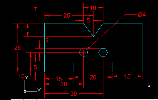

Absolute co-ordinate system

The Algorithm is:


PL
10,10
25,10
25,15
45,15
45,10
60,10
60,35
40,35
35,28
30,35
10,35
c
C
30,20
D
4
POL
6
40,20
C
2

5. Create the below shown drawing algorithm using Relative coordinate values:


Relative coordinate system


L
10,10
@15,0
@0,5
@20,0
@0,-5
@15,0
@0,25
@-20,0
@-5,-7
@-5,7
@-20,0
C
C
30,20
D
4
POL
6
40,20
C
2

Create the below shown drawing algorithm using Relative Polar coordinate values:


Relative Polar coordinate system


PL
0,0
@70<0
@28.3<45
@50<90
@28.3<135
@70<180
@28.3<225
@50<270
c
C
30,30
10
POL
6
30,60
C
10

We can create continuous line with Arc's elements and line elements using PL (Poly Line) command.



Back to AutoCAD all lessons

Comments

CAD tutor . net said…
Excellent examples shown for AutoCAD or Computer Aided Design algorithms. I really like this drawing algorithms and easy to understand all the CAD code. The way your explanation as step by step is very nice.

keep going brother...
autodesk.com said…
Really you did a great job. i liked your explanation and now i understand everything about the differences between co-ordinate systems used in AutoCAD software.

Recent posts

Welding-LAP JOINT

Ex. No :                                                                              Date : LAP JOINT Aim To join the given two work pieces as a lap joint by arc welding. Material used Mild Steel plates. Tools required Welding power supply  Flat file Welding rod Chipping hammer Electrode holder Wire brush Gloves and apron Earthing clamps Shield and goggles Procedure The given workpieces are thoroughly cleaned, i.e. rust, scales are removed and the  edges are filed. The electrode is held in an electrode holder and ground clamp is clamped to the  welding plates and the power is supplied. The workpieces are positioned on the table to form a “Lab joint”. The tag weld is done on the both the ends of joining plates to avoid the m...

Fluid mechanics VIVA QUESTIONS and ANSWERS

1. Define density? Ans: It is defined as the ratio of mass per unit volume of the fluid. 2. Define viscosity? Ans: It is defined as the property of fluid which offers resistance to the movement of fluid over another adjacent layer of the fluid. 3. Differentiate between real fluids and ideal fluids? Ans: A fluid, which is in-compressible and is having no viscosity, is known as ideal fluid while the fluid, which possesses viscosity, is known as real fluid. 4. What is a venturimeter? Ans: It is a device which is used for measuring the rate of flow of fluid flowing through pipe. 5. What is a notch? Ans: A notch is a device used for measuring the rate of flow of a fluid through a small channel or a tank. 6. Define buoyancy? Ans: When a body is immersed in a fluid, an upward force is exerted by the fluid on the body. This upward force is equal to the weight of the fluid displaced by the body. 7. Define meta-centre? Ans: It is defined as the point about which a body...

FACING, PLAIN TURNING AND STEP TURNING

Ex. No :                                                                                                          Date : FACING, PLAIN TURNING AND STEP TURNING Aim                       To perform turning, facing and chamfering on a cylindrical work piece. Material used                       Mild steel cylindrical rod. Tools required Lathe Three-jaw chuck Chuck key Vernier caliper Single-point cutting tool Procedure First loosen the jaw in the chuck key to position the work piece, and then tighten the  jaws. Fix the cutting tool in the toolpost. Switch on the lath...

Isometric drawings for practice in AutoCAD

What is Isometric Drawing? Isometric drawing is a method of visually representing three-dimensional objects in two dimensions. It allows for a clear and comprehensive depiction of complex structures by keeping the scale consistent and eliminating distortion. Isometric drawings use a 30-degree angle from the horizontal in all three axes (X, Y, and Z), creating a pseudo-3D effect where the height, width, and depth are equally foreshortened. Creating Isometric Drawings in AutoCAD AutoCAD provides tools and settings that make creating isometric drawings straightforward. Here’s a step-by-step guide: Step 1: Set Up Isometric Snap/Grid 1. Enable Isometric Snap/Grid:    - Type `SNAP` in the command line and press `Enter`.    - Type `Style` and press `Enter`.    - Choose `Isometric` and press `Enter`. 2. Switch Between Isoplanes:    - Type `F5` or `CTRL+E` to toggle between the top, right, and left isoplanes. Step 2: Draw Isometric Circles and Arcs 1. Isom...

MOULD WITH SPLIT PATTERN

Ex. No :                                                                                       Date : MOULD WITH SPLIT PATTERN Aim To make the mould for the given split pattern. Material required •  Moulding board •  Riser pin •  Moulding box •  Sprue pin •  Green sand •  Rammer •  Trowel •  Lifter •  Riddle •  Draw spike •  Gate cutter  •  Bellow •  Vent rod  Procedure 1. Place the moulding board on a horizontal surface. 2. The drag box is placed above the moulding board. Now one piece      of pattern is kept at  center of the drag as shown in figure. 3. The parting sand is spread before we keep the pattern. 4. Facing sand is spri...

SINGLE ‘V’ BUTT JOINT

Experiment No.:                                                                                      Date: SINGLE ‘V’ BUTT JOINT Aim: To prepare a single ‘V’ Butt Joint as per dimensions given in the sketch. Material Required: Mild Steel plates: 80mm X 40mm X 6mm = 2 Nos Mild Steel electrode ¢ 3.15 mm Equipment required: A.C. Transformer with all welding accessories like Electrode holder, cables. Tool Required: Steel rule 300mm  Scriber 150mm Flat file 300mm Try square 200mm Flat Tong 450mm  Chipping hammer 200mm Ball peen hammer 750mm  Wire brush Welding screen Sequence of Operations: 1. Marking  2. Filing  3. Welding  4. Finishing Procedure: Take two Mild steel plates of size 80mm X 40mm X 6mm. Fix the wor...
PLUMBING Introduction Plumbing deals with the laying of a pipeline. A craftsman may be perfectly proficient with the hammer, saw and other tools, but the faces difficulties with leaking pipes and overflowing toilets. Many people rush to a plumber on seeking a tripping pipe, but a person with a little knowledge of the sanitary system can control this problem easily, saving time and, one with help of few tools. Plumbing tools The tools used by a plumber can be classified as follows Pipe wrench  Pipe vice Pipe cutter Hacksaw  Dies Files and Rasps Plumb bob Pipe wrench A pipe wrench is used for holding and turning the pipes, rods and machine prts. Wrenches are classified as follows. 1.Fixed wrenches  2. Adjustable wrenches. Pipe vice A pipe vice is fitted on the work bench. This has a set of jaws to grip the pipe and prevent it from turning while cutting, threading and fitting of bends, couplings etc. The yoke vice is co...

Viva questions and answers about CNC (Computer Numerical Control)

Q1: What is CNC? A1: CNC stands for Computer Numerical Control. It is a technology that uses computerized systems to control machine tools and automate manufacturing processes. Q2: What are the advantages of CNC machining? A2: Some advantages of CNC machining include: Increased precision and accuracy in manufacturing. Improved efficiency and productivity. Greater flexibility in producing complex parts. Reduced human error and increased repeatability. Ability to automate manufacturing processes. Enhanced safety for operators. Q3: How does CNC differ from traditional machining? A3: CNC differs from traditional machining in that it uses computerized control systems to operate machine tools. Traditional machining relies on manual operation, while CNC machines can execute precise instructions based on digital design data. Q4: What are the primary components of a CNC system? A4: The primary components of a CNC system are: Machine tool: The physical equipment such as a lathe, mill, or router....

Calibration of pressure gauge using dead weight tester

Aim : On completion of this unit you will be able to check the accuracy of a Bourdon tube pressure gauge using dead weight tester. Theory : Many types of gauges are available for measurement of pressure. The Bourdon gauge (named after its inventor Bourdon) uses the deflection of a tube of oval cross-section to cause a pointer to move over a scale. Because of its simplicity and low cost, and the large selection of pressure ranges, which are available, the Bourdon gauge is widely used engineering practice. All pressure gauges, of whatever type, needs to be calibrated. As the calibration may change over a period, repeat calibrations may well be needed from time to time. The normal calibration procedure is to load the gauge with known pressures, using a dead weight tested using oil. The present experiment, however, works satisfactorily with oil. In this experiment we check the accuracy of the Bourdon Tube pressure gauge. The procedure will be to calibrate the gauge by applying weight...

Carpentry Viva Questions

Q1: Define carpentry? Ans:  Carpentry is a skilled trade that involves working with wood to construct, install, and repair structures and objects. It encompasses various tasks such as measuring, cutting, shaping, joining, and finishing wood to create functional and aesthetically pleasing products. Q2: What are the various types of wood material used in carpentry? Ans:  The various types of wood materials used in carpentry include softwoods (such as pine, fir, cedar, and spruce) and hardwoods (such as oak, maple, mahogany, and walnut). Other wood materials used in carpentry can include plywood, particleboard, MDF (medium-density fiberboard), and engineered wood products like laminated veneer lumber (LVL) and oriented strand board (OSB). Q3: What is the sequence of operations in carpentry? Ans:  The sequence of operations in carpentry typically involves planning and design, material selection and preparation, measuring and marking, cutting and shaping, joinery or fasteni...

Search This Blog