
Create 3D plot using MATLAB

Also Read


%save the function with name as plotcube.m

%function starts from here
function plotcube(varargin)
% PLOTCUBE - Display a 3D-cube in the current axes
%
%   PLOTCUBE(EDGES,ORIGIN,ALPHA,COLOR) displays a 3D-cube in the current axes
%   with the following properties:
%   * EDGES : 3-elements vector that defines the length of cube edges
%   * ORIGIN: 3-elements vector that defines the start point of the cube
%   * ALPHA : scalar that defines the transparency of the cube faces (from 0
%             to 1)
%   * COLOR : 3-elements vector that defines the faces color of the cube
%
% Example:
%   >> plotcube([5 5 5],[ 2  2  2],.8,[1 0 0]);
%   >> plotcube([5 5 5],[10 10 10],.8,[0 1 0]);
%   >> plotcube([5 5 5],[20 20 20],.8,[0 0 1]);
% Default input arguments
inArgs = { ...
  [5 5 5] , ... % Default edge sizes (x,y and z)
  [10 10  10] , ... % Default coordinates of the origin point of the cube
  1         , ... % Default alpha value for the cube's faces
  [1 0 0]       ... % Default Color for the cube
  };
% Replace default input arguments by input values
inArgs(1:nargin) = varargin;
% Create all variables
[edges,origin,alpha,clr] = deal(inArgs{:});
XYZ = { ...
  [0 0 0 0]  [0 0 1 1]  [0 1 1 0] ; ...
  [1 1 1 1]  [0 0 1 1]  [0 1 1 0] ; ...
  [0 1 1 0]  [0 0 0 0]  [0 0 1 1] ; ...
  [0 1 1 0]  [1 1 1 1]  [0 0 1 1] ; ...
  [0 1 1 0]  [0 0 1 1]  [0 0 0 0] ; ...
  [0 1 1 0]  [0 0 1 1]  [1 1 1 1]   ...
  };
XYZ = mat2cell(...
  cellfun( @(x,y,z) x*y+z , ...
    XYZ , ...
    repmat(mat2cell(edges,1,[1 1 1]),6,1) , ...
    repmat(mat2cell(origin,1,[1 1 1]),6,1) , ...
    'UniformOutput',false), ...
  6,[1 1 1]);
cellfun(@patch,XYZ{1},XYZ{2},XYZ{3},...
  repmat({clr},6,1),...
  repmat({'FaceAlpha'},6,1),...
  repmat({alpha},6,1)...
  );
view(3);

%save this program with another name
 axis([0 25 0 25 0 25]);

grid();

%function ends

%create new m-File and save cum run the program

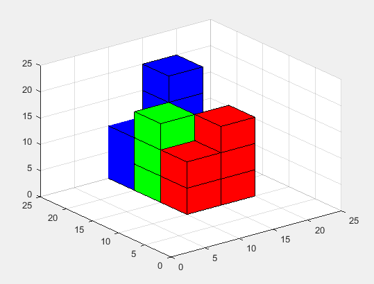
plotcube([10 10 10],[10 20 0],1,[0 0 1]);
  plotcube([5 5 5],[15 20 0],1,[0 0 1]);
   plotcube([5 5 5],[15 20 5],1,[0 0 1]);
    plotcube([5 5 5],[15 20 10],1,[0 0 1]);
     plotcube([5 5 5],[15 20 15],1,[0 0 1]);
 %creating greeen color cubes
 plotcube([5 5 5],[10 15 0],1,[0 1 0]);
 plotcube([5 5 5],[10 15 5],1,[0 1 0]);
 plotcube([5 5 5],[10 15 10],1,[0 1 0]);
  plotcube([5 5 5],[15 15 0],1,[0 1 0]);
  
  %creating red color cubes
 plotcube([5 5 5],[10 10 0],1,[1 0 0]);
 plotcube([5 5 5],[10 10 5],1,[1 0 0]);
  plotcube([5 5 5],[15 10 0],1,[1 0 0]);
 plotcube([5 5 5],[15 10 5],1,[1 0 0]);
 plotcube([5 5 5],[15 10 10],1,[1 0 0]);


Comments

Recent posts

Welding VIVA question and answers

VIVA QUESTIONS : Q1: Define welding? Ans:  Welding is a fabrication process that joins two or more materials, typically metals or thermoplastics, by melting and fusing them together using heat or pressure. Q2: What is the typical thickness of MS Plate used in general welding workshop experiments? Ans:  The thickness of the MS (Mild Steel) plate used in general welding workshop experiments can vary depending on the specific requirements of the experiment. However, commonly used thicknesses range from 3 mm to 12 mm. Q3: What is the common job material used in welding experiments? Ans:  The common job material used in welding experiments is mild steel. It is widely available, affordable, and relatively easy to work with, making it suitable for various welding applications and practice. Q4: What is the main function of an electrode in welding? Ans:  The main function of an electrode in welding is to carry the electric current necessary for the welding process and to ...

Welding-TEE FILLET JOINT

Ex. No :                                                                                 Date : TEE FILLET JOINT Aim To join the given two work pieces as a ‘Tee fillet joint’ by arc Welding. Material used Mild steel plates. Tools required • Welding power supply • Flat file • Welding rod • Chipping hammer • Electrode holder • Wire brush • Gloves and apron  • Earthing clamps • Shield and goggles Procedure The given workpieces are thoroughly cleaned, i.e. rust, scales are removed and the  edges are filed. The electrode is held in an electrode holder and ground clamp is clamped to the  welding plates and the power is supplied. The workpieces are positioned on the table to form a “Tee fillet joint”. The tag weld is done on the bo...

SINGLE ‘V’ BUTT JOINT

Experiment No.:                                                                                      Date: SINGLE ‘V’ BUTT JOINT Aim: To prepare a single ‘V’ Butt Joint as per dimensions given in the sketch. Material Required: Mild Steel plates: 80mm X 40mm X 6mm = 2 Nos Mild Steel electrode ¢ 3.15 mm Equipment required: A.C. Transformer with all welding accessories like Electrode holder, cables. Tool Required: Steel rule 300mm  Scriber 150mm Flat file 300mm Try square 200mm Flat Tong 450mm  Chipping hammer 200mm Ball peen hammer 750mm  Wire brush Welding screen Sequence of Operations: 1. Marking  2. Filing  3. Welding  4. Finishing Procedure: Take two Mild steel plates of size 80mm X 40mm X 6mm. Fix the wor...

Welding-LAP JOINT

Ex. No :                                                                              Date : LAP JOINT Aim To join the given two work pieces as a lap joint by arc welding. Material used Mild Steel plates. Tools required Welding power supply  Flat file Welding rod Chipping hammer Electrode holder Wire brush Gloves and apron Earthing clamps Shield and goggles Procedure The given workpieces are thoroughly cleaned, i.e. rust, scales are removed and the  edges are filed. The electrode is held in an electrode holder and ground clamp is clamped to the  welding plates and the power is supplied. The workpieces are positioned on the table to form a “Lab joint”. The tag weld is done on the both the ends of joining plates to avoid the m...

Isometric drawings for practice in AutoCAD

What is Isometric Drawing? Isometric drawing is a method of visually representing three-dimensional objects in two dimensions. It allows for a clear and comprehensive depiction of complex structures by keeping the scale consistent and eliminating distortion. Isometric drawings use a 30-degree angle from the horizontal in all three axes (X, Y, and Z), creating a pseudo-3D effect where the height, width, and depth are equally foreshortened. Creating Isometric Drawings in AutoCAD AutoCAD provides tools and settings that make creating isometric drawings straightforward. Here’s a step-by-step guide: Step 1: Set Up Isometric Snap/Grid 1. Enable Isometric Snap/Grid:    - Type `SNAP` in the command line and press `Enter`.    - Type `Style` and press `Enter`.    - Choose `Isometric` and press `Enter`. 2. Switch Between Isoplanes:    - Type `F5` or `CTRL+E` to toggle between the top, right, and left isoplanes. Step 2: Draw Isometric Circles and Arcs 1. Isom...

Welding-SQUARE BUTT JOINT

Ex. No:                                                                             Date : SQUARE BUTT JOINT Aim To join the given two work pieces as a ‘square butt joint’  by arc welding. Material used Mild steel plates. Tools required • Welding power supply  .• Flat file • Welding rod • Chipping hammer • Electrode holder • Wire brush • Gloves and apron  • Earthing clamps • Shield and goggles Procedure 1. The given workpieces are thoroughly cleaned, i.e. rust, scales are removed and the  edges are filed. 2. The electrode is held in an electrode holder and ground clamp is clamped to the  welding plates and the power is supplied. 3. The workpieces are positioned on the table form a “square butt joint”. 4. The tag weld is done on...

Fluid mechanics VIVA QUESTIONS and ANSWERS

1. Define density? Ans: It is defined as the ratio of mass per unit volume of the fluid. 2. Define viscosity? Ans: It is defined as the property of fluid which offers resistance to the movement of fluid over another adjacent layer of the fluid. 3. Differentiate between real fluids and ideal fluids? Ans: A fluid, which is in-compressible and is having no viscosity, is known as ideal fluid while the fluid, which possesses viscosity, is known as real fluid. 4. What is a venturimeter? Ans: It is a device which is used for measuring the rate of flow of fluid flowing through pipe. 5. What is a notch? Ans: A notch is a device used for measuring the rate of flow of a fluid through a small channel or a tank. 6. Define buoyancy? Ans: When a body is immersed in a fluid, an upward force is exerted by the fluid on the body. This upward force is equal to the weight of the fluid displaced by the body. 7. Define meta-centre? Ans: It is defined as the point about which a body...

step by step procedure to draw hook 2D drawing using AutoCAD

1. Create one vertical line and two horizontal lines like shown below according to dimensions. 2.Draw the circles at intersecting points like shown below with given dimensions. 3. Draw TTR (tangent tangent Radius) circles like shown below with given radius values. 4. Trim extra elements using " TR " command the final image be shown like below. 5. Now draw another reference lines and circles using TTR(tangent tangent Radius) circle according to given dimensions. 6. Now Trim the extra elements by using "TR" command. 7. Now dimension the elements using DIM command.

Coordinate systems in AutoCAD

World Coordinate System (WCS), User Coordinate System (UCS). There is 4 AutoCAD coordinates system you should know. Absolute coordinate system , Relative Rectangular coordinate system, Relative Polar coordinate system and Interactive system(Direct coordinate system). Absolute Coordinate system: Absolute Coordinates uses the Cartesian System to specify a position in the X, Y, and (if needed) Z axes to locate a point from the 0-X, 0-Y, and 0-Z (0,0,0) point. To locate a point using the Absolute Coordinate system, type the X-value, Y-value, and, if needed, the Z-value separated by commas (with no spaces). Syn: Enter LINE command: L [Enter] Start line at point A: 0,0 [Enter] End first line at point B: 2,2 [Enter] End of second line at point C: 2,3 [Enter] Examples shown bellow. Relative Rectangular Coordinate system: After first points entered, your next points can be entered by specifying the next coordinate compare/relative f...

Dovetail Joint

Ex.No:                                                                                                    Date Dovetail Joint   Aim To make the Dovetail joint the required dimensions from the given workpiece. Material Required Soft wood of size 300x50x50 mm. Tools Required 1. Jackplane 2. Carpentry vice 3. Try square 4. Mortise gauge 5. Mallet 6. Firmer chiesel Procedure The given workpiece is firmly clamped in the carpentry vice and any two adjacent s urfaces are planed to get right angles using the jack plane. Using the try square, the right angles of planned faces are checked. Now the other two surfaces are planned to get smooth surface. The workpiece is cut into two pieces by using the rip saw. Mark the di...

Search This Blog