
sheet metal introduction

Also Read

Sheet metal Introduction

Sheet Metal Introduction

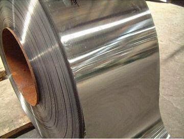
Sheet metal is simply metal formed into thin and flat pieces. It is one of the fundamental forms used in metalworking, and can be cut and bent into a variety of different shapes. Countless everyday objects are constructed of the material. Thicknesses can vary significantly, although extremely thin thicknesses are considered foil or leaf, and pieces thicker than 6 mm (0.25 in) are considered plate.


Uses of Sheet metal:-

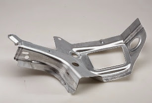
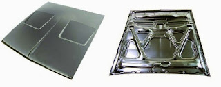
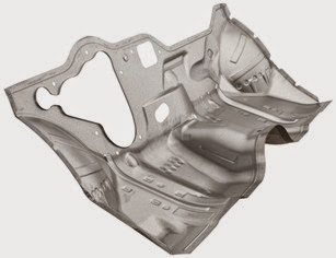
For making buckets, duct, pans, Gutters, tanks, boxes, food containers, dairy equipments, cans, radiators in automobiles, chemical plants, and domestic heating appliances, construction of airplanes, Refrigerators, house hold utensils and fabrication work for making bus bodies etc,. by using various metals like Galvanized iron(GI), Black iron, Tin plate, Stainless steel, Copper, Aluminum etc,..

Sheet metal Tools Required:-

Plate gauge:-

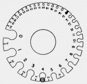
Used for measure thickness of sheets.
The most commonly used gauge in sheet metal has 21 slots with gauge numbers ranging from 4 to 24.


Steel rule:-

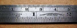
Used for taking linear measurement. The accuracy is 0.5mm in metric and 1/64 inch in British system.


Flexible push pull rule:-

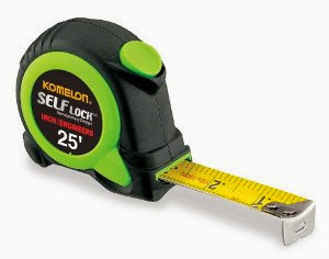
Used for measuring long dimensions. Generally the maximum length of the role is 10meters


Scriber :-

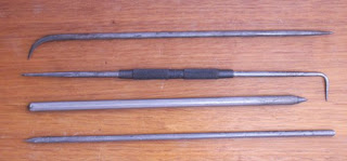
Used when we draw marking lines on metal surface.


Divider:-

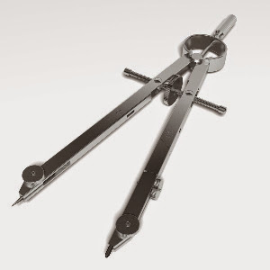
It is used for transferring the sizes.Scribing curves, Circles on a sheet metal with small raids.


Trammel points:-

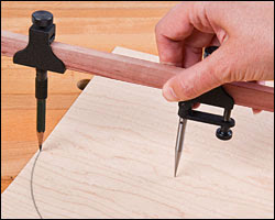
Used for drawing very large circles and arcs on sheet metal surface.


Steel square(Try square):-

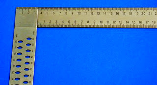
Used for accurate laying out work. For marking dimensions perpendicular to any base.


Semi circular protractor:-

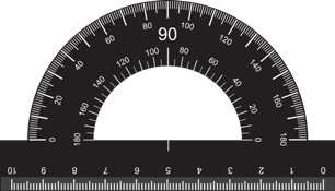
Used for setting bevels, transferring angles. The indicating arm of the blade has line graduations for accurately setting and reading the protractor.


Punch:-

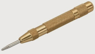
Made with tool steel. The point and head is hardened and tempered. Shank is knurled to provide grip.The point angle is 60 degrees to 90 degrees.Used to punch dotted lines on sheet metal.


Mallet:-

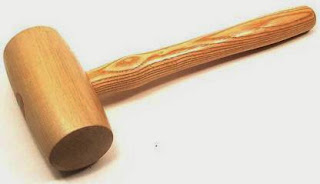
Used whenever light blows are required.
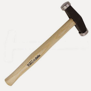

Riveting hammer :-

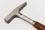
Used for forming rivet heads


Raising hammer:-

Used for making depressions with a flat chisel.Used for removing small marks or indentations from the job surface. To true the shape of the work and to smoothen finished work


Back button

Comments

Andrea Lim said…
Thank You Very Much For Great Post Find here Stainless Steel Sheet, SS Sheets manufacturers, suppliers & exporters in Singapore. Get contact details & address of companies manufacturing Stainless Steel Sheets
Wow, I came to learn about Mild Steel Fabrication, and your information is absolutely amazing! For more insights and if your are looking for the Best Mild Steel Fabrication Services in India, check out Divine Technozone! We specialize in reliable solutions to meet all your fabrication solution. Keep up the great work!

Recent posts

Isometric drawings for practice in AutoCAD

What is Isometric Drawing? Isometric drawing is a method of visually representing three-dimensional objects in two dimensions. It allows for a clear and comprehensive depiction of complex structures by keeping the scale consistent and eliminating distortion. Isometric drawings use a 30-degree angle from the horizontal in all three axes (X, Y, and Z), creating a pseudo-3D effect where the height, width, and depth are equally foreshortened. Creating Isometric Drawings in AutoCAD AutoCAD provides tools and settings that make creating isometric drawings straightforward. Here’s a step-by-step guide: Step 1: Set Up Isometric Snap/Grid 1. Enable Isometric Snap/Grid:    - Type `SNAP` in the command line and press `Enter`.    - Type `Style` and press `Enter`.    - Choose `Isometric` and press `Enter`. 2. Switch Between Isoplanes:    - Type `F5` or `CTRL+E` to toggle between the top, right, and left isoplanes. Step 2: Draw Isometric Circles and Arcs 1. Isom...

SINGLE ‘V’ BUTT JOINT

Experiment No.:                                                                                      Date: SINGLE ‘V’ BUTT JOINT Aim: To prepare a single ‘V’ Butt Joint as per dimensions given in the sketch. Material Required: Mild Steel plates: 80mm X 40mm X 6mm = 2 Nos Mild Steel electrode ¢ 3.15 mm Equipment required: A.C. Transformer with all welding accessories like Electrode holder, cables. Tool Required: Steel rule 300mm  Scriber 150mm Flat file 300mm Try square 200mm Flat Tong 450mm  Chipping hammer 200mm Ball peen hammer 750mm  Wire brush Welding screen Sequence of Operations: 1. Marking  2. Filing  3. Welding  4. Finishing Procedure: Take two Mild steel plates of size 80mm X 40mm X 6mm. Fix the wor...

Fluid mechanics VIVA QUESTIONS and ANSWERS

1. Define density? Ans: It is defined as the ratio of mass per unit volume of the fluid. 2. Define viscosity? Ans: It is defined as the property of fluid which offers resistance to the movement of fluid over another adjacent layer of the fluid. 3. Differentiate between real fluids and ideal fluids? Ans: A fluid, which is in-compressible and is having no viscosity, is known as ideal fluid while the fluid, which possesses viscosity, is known as real fluid. 4. What is a venturimeter? Ans: It is a device which is used for measuring the rate of flow of fluid flowing through pipe. 5. What is a notch? Ans: A notch is a device used for measuring the rate of flow of a fluid through a small channel or a tank. 6. Define buoyancy? Ans: When a body is immersed in a fluid, an upward force is exerted by the fluid on the body. This upward force is equal to the weight of the fluid displaced by the body. 7. Define meta-centre? Ans: It is defined as the point about which a body...

Step by step procedure to insert 3rd Angle Projection symbol in Solidworks

Step 1: open solidworks drawing tool with default or your required sheet size. Then the object view in paper space. Step 2: 1. Click on Annotation tab and select "Note". 2. Then add the note at title block. 3. Then click on add symbol in properties manager. 4. Then click on add more symbols. Step 3: Check the symbol in symbol library categories. if you found the symbol then click on "OK" button. if you not found the 3rd angle projection in the symbol library categories then see the Step 4 in this page. Step 4: 1. Go to this file location from your computer by pasting the below in your windows explorer or browse from your computer or search "gtol.sym" and open the file location by using right clicking on the searchable file. C:\ProgramData\SOLIDWORKS\SOLIDWORKS 2019\lang\english 2. Then copy the "gtol.sym" file then paste this file in anywhere you like. here i'm pasting this file in desktop > Solidworks > pr...

Welding introduction

WELDING Introduction : Welding is a process of joining two similar or dissimilar metals by the application of heat with or without application of pressure and addition of filler material. The welding is extensively used in manufacturing industry, construction industry and maintenance work, replacing riveting and bolting, to a greater extent.  The various welding processes are 1. Electric arc welding 2. Gas welding 3. Thermit welding 4. Resistance welding and 5. Friction welding However only electric arc welding is discussed here. In this process, the work pieces are melted along a common edge, to their melting point and then a filler metal is introduced to form the joint on solidification. The materials to be welded must be free from rust, scale oil or other impurities, so as to obtain a sound weld. Arc Welding: In arc welding, the heat required for joining the metals is obtained from an electric arc. Transformers or motor generator sets are used as arc welding ma...

Welding VIVA question and answers

VIVA QUESTIONS : Q1: Define welding? Ans:  Welding is a fabrication process that joins two or more materials, typically metals or thermoplastics, by melting and fusing them together using heat or pressure. Q2: What is the typical thickness of MS Plate used in general welding workshop experiments? Ans:  The thickness of the MS (Mild Steel) plate used in general welding workshop experiments can vary depending on the specific requirements of the experiment. However, commonly used thicknesses range from 3 mm to 12 mm. Q3: What is the common job material used in welding experiments? Ans:  The common job material used in welding experiments is mild steel. It is widely available, affordable, and relatively easy to work with, making it suitable for various welding applications and practice. Q4: What is the main function of an electrode in welding? Ans:  The main function of an electrode in welding is to carry the electric current necessary for the welding process and to ...

Welding-LAP JOINT

Ex. No :                                                                              Date : LAP JOINT Aim To join the given two work pieces as a lap joint by arc welding. Material used Mild Steel plates. Tools required Welding power supply  Flat file Welding rod Chipping hammer Electrode holder Wire brush Gloves and apron Earthing clamps Shield and goggles Procedure The given workpieces are thoroughly cleaned, i.e. rust, scales are removed and the  edges are filed. The electrode is held in an electrode holder and ground clamp is clamped to the  welding plates and the power is supplied. The workpieces are positioned on the table to form a “Lab joint”. The tag weld is done on the both the ends of joining plates to avoid the m...

step by step procedure to draw hook 2D drawing using AutoCAD

1. Create one vertical line and two horizontal lines like shown below according to dimensions. 2.Draw the circles at intersecting points like shown below with given dimensions. 3. Draw TTR (tangent tangent Radius) circles like shown below with given radius values. 4. Trim extra elements using " TR " command the final image be shown like below. 5. Now draw another reference lines and circles using TTR(tangent tangent Radius) circle according to given dimensions. 6. Now Trim the extra elements by using "TR" command. 7. Now dimension the elements using DIM command.

Sheet metal Funnel making

Making a Funnel using metallic sheet Making a Funnel using metallic sheet Aim:- To make a funnel from a given (GI)metallic sheet. Tools Required:- MALLET, SNIP, STAKE, STEEL RULE, BALL PEEN HAMMER, STRAIGHT EDGE, RIVETS, SCRIBER Procedure:  The size of the given sheet metal is checked for its dimensions using a steel rule The required development of surface is being made on the white paper which is overlapped on the sheet metal. The marking is done on the sheet metal as per the development being done on the paper. Now using straight snips, unwanted materials are removed. Now fold and bend the workpiece to make the funnel shape and joint is made on the workpieces. Then using a groover, a locked grooved joint is made for about 5mm. Also, hemming is done in the bottom of the funnel. In between top face and bottom face, a butt joint is made using a solder. Finally, trimming and finishing operations are carried out. Safety Precautions:- Each cut you make exposes s...

ROCKWELL HARDNESS TEST

Aim :-To determine the Rockwell hardness for the given test specimen Equipment :-Rockwell Hardness Testing Machine,suitable indenter, test specimens. Description :-Hardness may be defined as resistance of metal to plastic deformation usually by indentation. However the term may also refer to stiffness or temper or resistance to scratch, abrasion or cutting. There are three general types of hardness measurements depending upon the manner in which the test is conducted. Scratch hardness measurement. Rebound hardness measurement. Indentation Hardness measurement. In scratch hardness method the materials are rated on their ability to scratch one another and mineralogists use it. In rebound hardness measurement, a standard body is usually dropped on to the material surface and the hardness is measured in terms of the height of its rebound. The general means of judging the hardness is the resistance of a material to indentation. Indentation hardness may be measured by various h...

Search This Blog