

Also Read
It is the combination of physical, mathematical, and computer laws and techniques to predict the behavior of solid materials that are subjected to mechanical or thermal loading. It is the branch of mechanics that deals with the behavior of solid matter under external actions. The external actions may be:

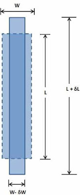 When a body is subjected to an external force, there is some change of dimension in the body. Numerically the strain is equal to the ratio of change in length to the original length of the body.
Primary Strain/Longitudinal Strain/Direct Strain:
Primary Strain/Longitudinal Strain/Direct Strain. It is the ratio of the change in longitudinal length (dimension parallel to the direction of applied force) to the original longitudinal length.
Longitudinal Strain = δL / L
Secondary Strain/Lateral Strain/indirect Strain
It is the ratio of the change in lateral dimension (dimension not parallel to the direction of applied force) to the original lateral dimension.
Lateral Strain = δW / W
This law states that when a material is loaded, within its elastic limit, the stress is directly proportional to the strain.
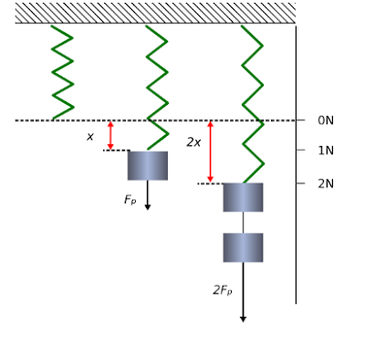 Stress α Strain
σ α ε
σ = Eε
E = σ/ε
Its unit is same as that of Stress
Where,
– E is Young’s modulus
– σ is Stress
– ε is Strain
Young’s Modulus:
It is the ratio of the normal stress to the normal strain. or It is the modulus of elasticity. This means it is a number which represents how easy it is to deform (stretch a material).
E = σ/ε
Measurement of the Young'sModulus
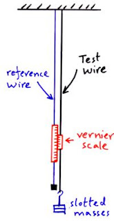 The Young Modulus for a wire can be measured using this equipment. The reference wire and test wire are hung from the ceiling. The reference wire supports a vernier scale which will measure the extension of the test wire. The force on the test wire can be varied using the slotted masses.
Measurements needed;
1) The original length of the test wire (L) should be measured with a tape measure.
2) The cross-sectional area (A) can be calculated from measuring the wires diameter with a micrometer. The micrometer should be used to measure the diameter at several different points along the wire.
3) The test wire will have several different forces (F) applied using the slotted masses and each time the extension of the test wire (DL) will be measured using the vernier scale.
Various materials Young'smodulus
 Steel - Young's module: 200GPa
Cast iron - Young's module: 100GPa
Concrete - Young's module: 20.0x10⁹ E(Pa)n below.
Poissons Ratio
 It is the ratio of the lateral strain to the longitudinal strain and is constant property of each material.
Poisson’ ratio (μ or 1/m) =
Lateral strain /Longitudinal strain.
Poisson's ratio is sometimes also reffered to as the ratio of the absolute values of lateral and axial strain. This ratio, like strain, is unitless since both strains are unitless. For stresses within the elastic range, this ratio is approximately constant. For a perfectly isotropic elastic material, Poisson's Ratio is 0.25, but for most materials the value lies in the range of 0.28 to 0.33. Generally for steels, Poisson's ratio will have a value of approximately 0.3. This means that if there is one inch per inch of deformation in the direction that stress is applied, there will be 0.3 inches per inch of deformation perpendicular to the direction that force is applied.
Rigidity Modulus:
 Its is the ratio of the shear stress to the shear strain.
N = Shear stress/Shear strain
N = τ/G
- External Force
- Temperature Change
- Displacement
Applications of Solid Mechanics:
- In Mechanical Engineering to design load bearing components for vehicles, power generation and transmission.
- In Civil Engineering to design foundations and structures.
- In Geo-Mechanics to model shape of planets, tectonics and predict earthquakes.
Stress
When an external force is applied on a body, it undergoes deformation which is resisted by the body. The magnitude of the resisting force is numerically equal to the applied force. This internal resisting force per unit area of the body is known as stress.
(or)
Stress is "force per unit area" - the ratio of applied force F to cross section area - defined as "force per area".
Stress = Resistive Force/Area
In equation form: σ = P/A,
Units are N/m2, kN/m2 MPa (Mega Pascal),
Psi (lb/in2), psf (lb/ft2)
Ksi (kips/in2), ksf (kips/ft2)

- Tensile stress :- Stress that tends to stretch or lengthen the material - acts normal to the stressed area.
Example - Tensile Force acting on a Rod
A force of 10 kN is acting on a circular rod with diameter 10 mm. The stress in the rod can be calculated as
σ = (10*103 N) / (π ((10*10-3 m) / 2)2)= 127388535 (N/m2)= 127 (MPa) - Compressive stress :- Stress that tends to compress or shorten the material - acts normal to the stressed area.
Example - Force acting on a Douglas Fir Square PostA compressive load of 30000 lb is acting on short square 6 x 6 in post of Douglas fir. The dressed size of the post is 5.5 X 5.5 in and the compressive stress can be calculated as
σ = (30000 lb) / ((5.5 in) (5.5 in))= 991 (lb/in2, psi) - Shearing stress :- Stress that tends to shear the material - acts in plane to the stressed area at right-angles to compressive or tensile stress.
Strain(Deformation)
 When a body is subjected to an external force, there is some change of dimension in the body. Numerically the strain is equal to the ratio of change in length to the original length of the body.
Strain = Change in length/Original length
In equation form: ε= δL/L
Units No units (unit less)
Primary Strain/Longitudinal Strain/Direct Strain:
Primary Strain/Longitudinal Strain/Direct Strain. It is the ratio of the change in longitudinal length (dimension parallel to the direction of applied force) to the original longitudinal length.
Longitudinal Strain = δL / L
Secondary Strain/Lateral Strain/indirect Strain
It is the ratio of the change in lateral dimension (dimension not parallel to the direction of applied force) to the original lateral dimension.
Lateral Strain = δW / W
Example - Stress and Change of Length The rod in the example above is 2 m long and made of steel with Modulus of Elasticity 200 GPa (200 109 N/m2). The change of length can be calculated by transforming (3) as
dl = σ lo / E
= (127*106 Pa) (2 m) / (200*109 Pa)
= 0.00127 (m)
= 1.27 (mm)
Hooke’s Law, Stress And StrainThis law states that when a material is loaded, within its elastic limit, the stress is directly proportional to the strain.

σ α ε
σ = Eε
E = σ/ε
Its unit is same as that of Stress
Where,
– E is Young’s modulus
– σ is Stress
– ε is Strain
Young’s Modulus:
It is the ratio of the normal stress to the normal strain. or It is the modulus of elasticity. This means it is a number which represents how easy it is to deform (stretch a material).
E = σ/ε
Measurement of the Young'sModulus
 The Young Modulus for a wire can be measured using this equipment. The reference wire and test wire are hung from the ceiling. The reference wire supports a vernier scale which will measure the extension of the test wire. The force on the test wire can be varied using the slotted masses.
Measurements needed;
1) The original length of the test wire (L) should be measured with a tape measure.
2) The cross-sectional area (A) can be calculated from measuring the wires diameter with a micrometer. The micrometer should be used to measure the diameter at several different points along the wire.
3) The test wire will have several different forces (F) applied using the slotted masses and each time the extension of the test wire (DL) will be measured using the vernier scale.
Various materials Young'smodulus

Cast iron - Young's module: 100GPa
Concrete - Young's module: 20.0x10⁹ E(Pa)n below.
Poissons Ratio
It is the ratio of the lateral strain to the longitudinal strain and is constant property of each material.Poisson’ ratio (μ or 1/m) =
Lateral strain /Longitudinal strain.
Poisson's ratio is sometimes also reffered to as the ratio of the absolute values of lateral and axial strain. This ratio, like strain, is unitless since both strains are unitless. For stresses within the elastic range, this ratio is approximately constant. For a perfectly isotropic elastic material, Poisson's Ratio is 0.25, but for most materials the value lies in the range of 0.28 to 0.33. Generally for steels, Poisson's ratio will have a value of approximately 0.3. This means that if there is one inch per inch of deformation in the direction that stress is applied, there will be 0.3 inches per inch of deformation perpendicular to the direction that force is applied.
Rigidity Modulus:

N = Shear stress/Shear strain
N = τ/G



Comments
black magic problem solution